Most homeowners and planners find that soakaways offer a practical method to manage surface water where you control runoff at source; by directing water into the ground you can achieve effective flood reduction and promote local recharge, but you must assess soil and proximity to structures because poorly sited systems risk groundwater contamination and structural damage. For technical guidance on design options consult Soakaways, Infiltration Trenches and Chambers to choose a sustainable, low-maintenance solution that suits your site.
Principles of Soakaways
Mechanisms of infiltration and attenuation
You assess soil permeability to size a soakaway: typical infiltration rates range from 1-100 mm/hr depending on texture and compaction. Water is temporarily stored in the void space and attenuated by filtration, sedimentation and microbial degradation, lowering peak flows and pollutant loads. Performance falls rapidly if silt or oil causes clogging, so planned access is important. Any routine inspection should occur at least annually and after major storms.
- Infiltration rate: varies 1-100 mm/hr
- Attenuation: filtration, sedimentation, biodegradation
- Storage: temporary void-space buffering peak flows
- Maintenance: inspections and desilting prevent failure
| Mechanism | Primary effect |
| Infiltration | Drains water into subsoil; rate 1-100 mm/hr |
| Filtration | Traps particles in pores and media |
| Sedimentation | Settles coarse solids before infiltration |
| Biological attenuation | Breaks down organics and hydrocarbons |
Soakaway types and system configurations
You select from stone-filled pits, permeable trenches, infiltration basins or modular crate systems; pits are simple, crates deliver high void ratios (~0.6-1.0 m³/m²). Guidance such as CIRIA C753 informs sizing and setbacks; maintain >1 m separation to groundwater where possible because high groundwater raises failure risk. Any design must include access for inspection and desilting to sustain long-term performance.
- Stone-filled pit: low cost, simple construction
- Permeable trench: linear infiltration for drives/paths
- Infiltration basin: surface storage for larger catchments
- Modular crate: high void ratio, compact footprint
| Type | Typical feature |
| Stone pit | Depth 0.5-2.0 m; simple |
| Modular crate | Void ratio 0.6-1.0 m³/m² |
| Permeable trench | Linear conveyance for narrow areas |
| Infiltration basin | Surface storage for yards/parks |
You can scale modular systems with examples: a 100 m² roof and a 50 mm storm produce 5.0 m³ runoff, so a crate array offering ~0.8 m³/m² voids needs about 6.25 m² footprint. Designers often allow 10-30% extra capacity for blockage and sediment accumulation, and inspections are typically every 1-3 years with immediate checks after heavy events. Any operational plan should record volumes, inspection dates and remedial actions to preserve infiltration rates.
- Runoff calc: 100 m² × 50 mm = 5.0 m³
- Void ratio: modular crates ~0.6-1.0 m³/m²
- Siting: >1 m to groundwater where achievable
- Maintenance: inspect annually, desilt every 1-3 years
| Parameter | Example value |
| Roof area | 100 m² |
| Storm depth | 50 mm |
| Storage required | 5.0 m³ |
| Crate footprint (0.8 m³/m²) | ≈6.25 m² |
Site Assessment and Investigation
Infiltration testing and soil characterisation
You should open trial pits to at least 1-1.5 metres, logging horizons and identifying clay seams or gravel lenses, then run falling‑head or single‑ring percolation tests; infiltration rates >1×10⁻⁵ m/s indicate highly permeable ground, while rates <1×10⁻⁷ m/s usually require attenuation or lined systems. Use undisturbed samples for laboratory permeability (constant/head) and perform particle‑size analysis and Atterberg limits to confirm soil behaviour under sustained loads.
Groundwater, contamination and constraint mapping
You must map seasonal groundwater levels and nearby hazards: if the water table sits within 1 metre of the proposed soakaway invert the feature is often unsuitable. Cross‑check Environment Agency/BGS data, local boreholes and historical land‑use to flag petrol stations, landfill or chemical yards that elevate risk of mobilisation into aquifers.
Beyond mapping, you should order targeted groundwater sampling for VOCs, TPH and metals where historic uses exist, and compare results to drinking‑water standards and local receptor sensitivities. Liaise with regulators early-Environment Agency constraints or Source Protection Zones may force engineered liners, oil separators, or discharge consents-so integrate hydrogeological modelling and risk assessment into your design stage.
Design and Sizing
You size soakaways from your site’s infiltration rate and runoff volume; a percolation test should inform whether soils drain at <1 mm/h (unsuitable) or >50 mm/h (excellent). For small roofs the Rational method helps, while larger catchments need hydrograph modelling; aim to attenuate the 1-in-30‑year storm plus 30% climate change. For practical examples and case studies see The Essential Role of Soak away Pits in Modern Construction.
Hydraulic calculation methods and storage requirements
You apply the Rational method (Q = C·i·A) for catchments under about 1 ha; beyond that, use continuous simulation tools such as MicroDrainage or SWMM to capture duration and serial storms. Typical infiltration rates span <1 to >100 mm/h, so compute storage as the difference between peak runoff and infiltration over the drainage time; for example, a 500 m² impermeable area with a 30 mm storm typically needs around 15 m³ of attenuation.
Integration with drainage networks and SuDS
You should position soakaways as the first SuDS element, combining permeable paving, swales and attenuation basins to maximise infiltration; where soils fail, provide an overflow to the public sewer with a flow control limiting discharge to an agreed rate (commonly around 5 litres per second (5 l/s) for small sites). Include pre-treatment, inspection chambers and clear exceedance routes to prevent silt or hydrocarbon pollution of groundwater.
When tying soakaways into existing drainage you must verify invert levels so gravity flow is maintained and the overflow discharges without surcharge; fit a vortex or hydrobrake to set discharge and include a bypass for extreme events. Also agree outfall rates with the sewerage undertaker, provide accessible chambers for maintenance, and ensure pre-treatment-insufficient detailing can cause sewer surcharge and contamination.
Siting, Planning and Regulatory Considerations
You must position soakaways with both geotechnical reality and regulatory policy in mind: common practice is to keep at least 5 metres from building foundations, maintain a minimum of 1 metre clearance to the seasonal high groundwater, and avoid locations that drain onto neighbouring property or into sewers. In practice you’ll design for a 1-in-30 to 1-in-100-year storm (depending on local policy), use infiltration testing to confirm suitability, and factor in climate-change allowances specified by local guidance.
Setbacks, easements and proximity to structures
When siting a soakaway you must preserve utility corridors, tree root zones and foundations: typically keep >5 metres from buildings, >2-3 metres from boundary walls and out of overlap with known drainage runs. Always consult utility plans and carry out CCTV where drains lie nearby; installing a soakaway over services or within root zones risks collapse, service damage and costly remedial works.
Permits, standards and local authority requirements
You’ll usually need to submit a drainage strategy, percolation/infiltration test results (BRE 365 methodology is widely referenced), and calculations showing storage for design storms to the local authority or SuDS approval body. Additionally, environmental consents from the Environment Agency/SEPA may be required where discharges affect watercourses; failure to obtain approval can lead to enforcement or removal orders.
Provide a clear maintenance plan, long-term ownership details and as-built records to expedite approval: authorities commonly ask for long-term performance commitments, an adoption offer or a legal easement, and evidence that design meets national standards (Building Regulations Part H, BRE guidance) plus any local SuDS policies. In marginal infiltration sites you should include contingency designs (such as overflow routes to sewers with separate consent) to demonstrate resilience and reduce refusal risk.
Materials and Construction Techniques
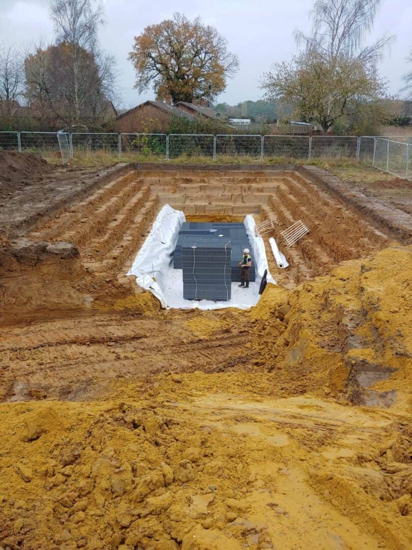
Use clean, angular crushed stone (20-40 mm) or modular plastic crates with a high void ratio to maximise storage and infiltration; modern crates typically deliver >90% void ratio and module heights of 300-600 mm. You should specify a non-woven geotextile (≈300 g/m²) to prevent fines and a 150 mm stone bedding layer. For context, a 100 m² roof with a 30 mm storm yields ~3 m³ of runoff, so plan storage and conveyance accordingly to meet that demand.
Component selection: crates, stone, geotextiles
You’ll choose between loose stone and modular crates based on space and infiltration needs: stone gives larger surface contact for faster infiltration per m³, while crates save excavation volume and are lighter to install. Specify clean, angular 20-40 mm stone, non-woven geotextile (300 g/m²) with 300 mm overlap, and crates with documented void ratio and load ratings. Insist on manufacturer data for storage capacity and structural performance under design loads.
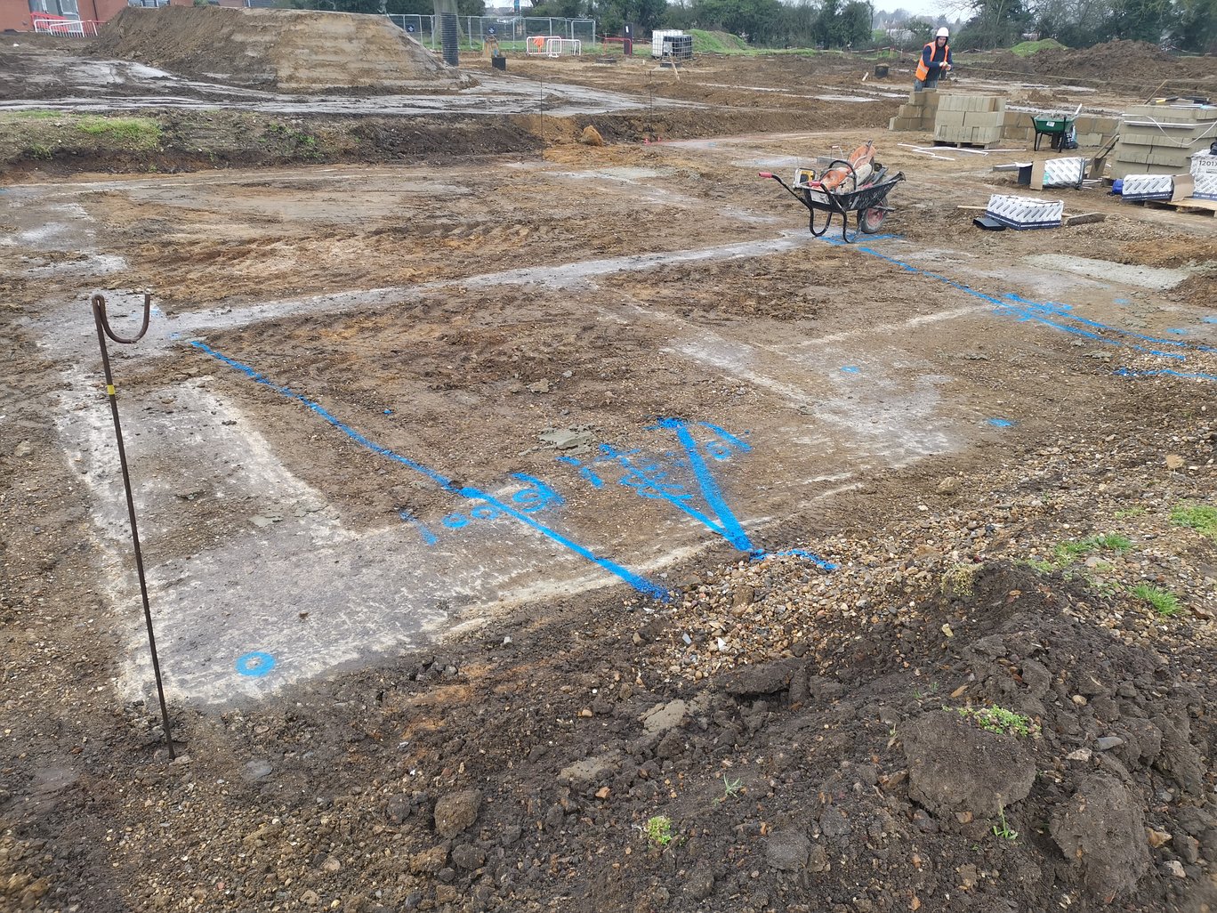
Installation best practice and quality control
Excavate to design depth and lay a 150 mm stone bedding, then place crates or stone, wrap with geotextile and backfill in 150-300 mm lifts with free-draining material. Maintain a typical cover of 300-600 mm over crates, avoid heavy plant within the infiltration zone, and conduct percolation testing and CCTV of pipework. Highlight risk of silting and protect with silt traps and pre-commissioning flushing.
During QA you must record as-built drawings, verify geotextile integrity and crate alignment, and log percolation results; keep inspection chambers accessible within 1 m of inlets. Place soakaways a minimum of 5 m from building foundations, perform a full commissioning flush, and consider a small safety factor (for example +10% storage) where infiltration variability is suspected.
Operation, Maintenance and Performance Management
You maintain soakaway effectiveness by integrating routine inspections, scheduled cleaning and targeted monitoring into your asset plan. Conduct visual checks every 6 months and after intense rainfall (> 25 mm in 24 hours), log all actions and prioritise high-risk catchments such as roads and car parks where sediment loads accelerate decline; consistent upkeep can prevent losses of performance exceeding 50% over ten years.
Inspection, cleaning and maintenance schedules
Schedule visual inspections every 6 months and after storms over 25 mm in 24 hours. Desilt chambers when sediment depth exceeds 50 mm or when you note ponding; typical cleaning cycles range from 1-5 years depending on catchment sediment load. Keep a maintenance log with dates, CCTV reports and photographs to support warranty and asset-management decisions.
Monitoring, failure modes and remediation
Use piezometers or level loggers to track water levels during the first 12 months and supplement with periodic CCTV and percolation testing so you can quantify decline. Common failure modes are clogging by fines, root ingress and structural collapse; warning signs include ponding for > 48 hours or sharp drops in infiltration. Remediation ranges from jetting and vacuum extraction to partial excavation and replacement of aggregate or geotextile.
During commissioning, install data loggers at 15-minute intervals and monitor weekly for the first 3 months, then monthly up to 12 months; if ponding persists beyond 48 hours or infiltration falls below 20% of the design rate, schedule action. Typical remediation restores performance by removing the top 0.3-0.6 m of fouled stone and replacing the geotextile, with structural repair only after trial pits/CCTV confirm collapse.
Summing up
Presently you should view soakaways as an effective means of managing surface water, reducing runoff and protecting structures; you must assess site suitability, installation standards, inspection and maintenance regimes, and regulatory compliance – consult Understanding Soakaways: A Comprehensive Guide to inform your design and upkeep choices.